| 1 | Tiny PC | Hardware · PCB · 3D Printing |
| 2 | Multithreaded PWM Timestamping System | Firmware · Embedded C · BeagleBone |
| 3 | Network Topology Analysis & Routing | Algorithms · Networking · Python |
| 4 | Microgrid Energy Consumption Prediction | Machine Learning · Scikit-Learn |
| 5 | Timing Side-Channel Attack & Defense | Cybersecurity · Python · Raspberry Pi 5 |
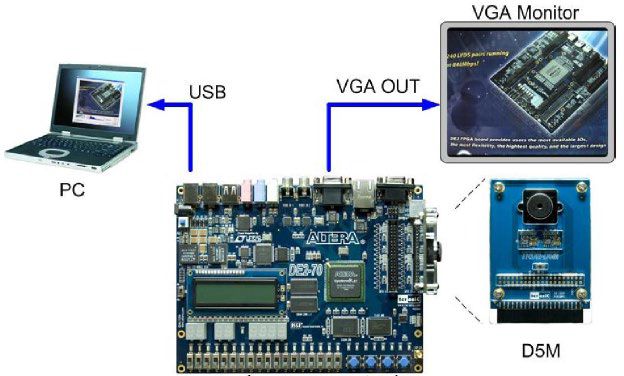
| 6 | Video Capture & Image Processing — DE1-SoC | FPGA · ARM Cortex-A9 · Embedded Vision |

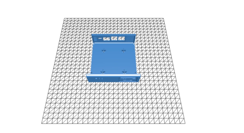
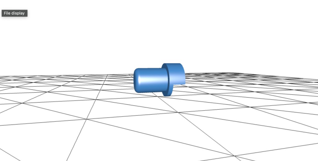
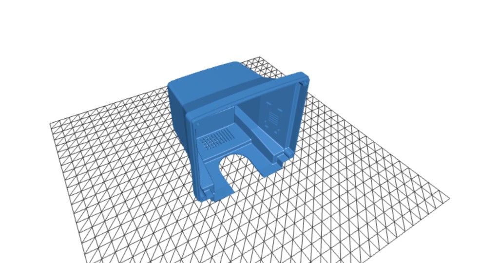
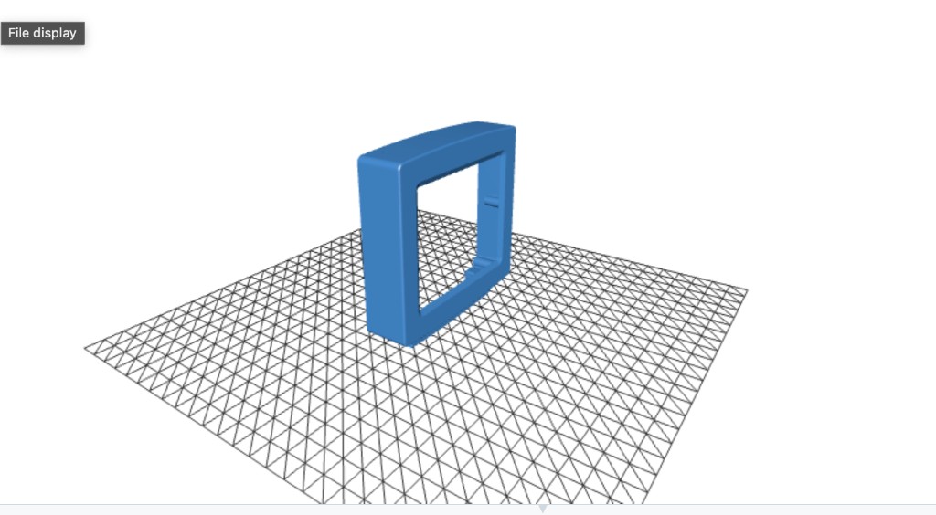
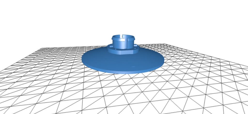
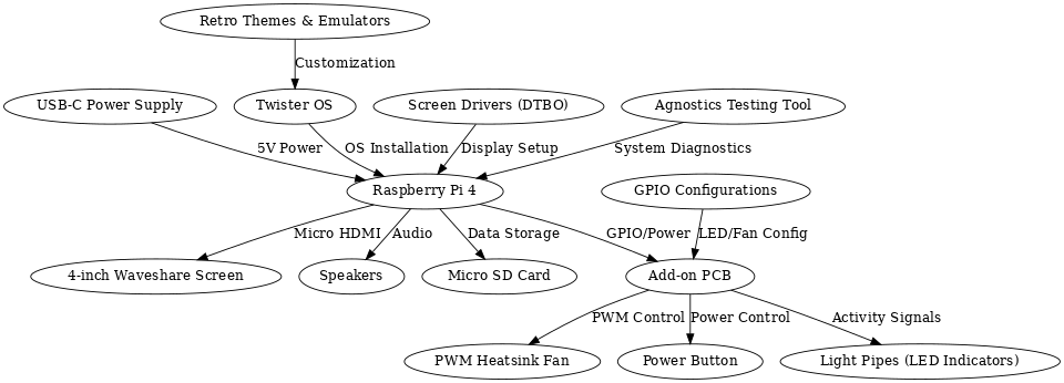
A fully functional miniature PC inspired by the classic computers of the 1990s and early 2000s. Combines 3D printing, custom PCB soldering, and software configuration into a palm-sized retro machine powered by a Raspberry Pi 4.
Design & Build Process
Downloaded STL files and studied the layout to plan how all enclosure parts interconnect.
Printed all parts at 50-micron resolution using ABS filament for strength and fine detail.
Soldered SMD components on a custom add-on PCB using a hot plate, including a USB-C port.
Wired a 4-inch Waveshare screen via HDMI and connected speakers with JST-PH connectors.
Installed Twister OS and configured screen overlays, GPIO LEDs, and PWM fan control.
Mounted screen to bezel, secured Pi with heatsink, routed cables, and added rubber feet.
Raspberry Pi 4
4" Waveshare Screen
Custom Add-on PCB
PWM Heatsink + Fan
15W USB-C Power Supply
ABS 3D-Printed Enclosure
Twister OS


Timestamping System
An event-driven embedded system built on the BeagleBone Black that captures 50 GPIO interrupt timestamps generated by an external PWM signal — without continuous polling. A producer thread waits on epoll for rising-edge interrupts and logs nanosecond timestamps into a mutex-protected shared buffer; a consumer thread writes all 50 records to disk and the terminal on completion.
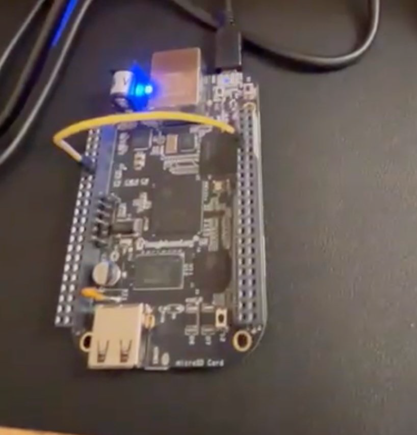
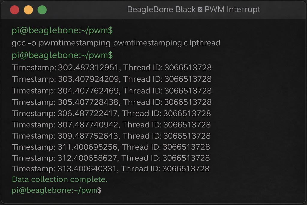
Two POSIX threads share a fixed-size buffer (SIZE=50) protected by a single pthread_mutex_t. The input thread configures P8_09 as a rising-edge GPIO interrupt via the sysfs interface and Linux epoll, then blocks on epoll_wait(). On each interrupt it acquires the mutex, writes clock_gettime(CLOCK_MONOTONIC) and pthread_self() into the buffer, and releases. The output thread sleeps 100ms per iteration until all 50 samples are collected, then writes every record to both stdout and a named text file.
while (bufferindex < SIZE) {
    epoll_wait(epfd, &ev_wait, 1, -1);        // block — no CPU polling
    clock_gettime(CLOCK_MONOTONIC, &tm);      // nanosecond timestamp
    pthread_mutex_lock(&lock);
    buffer[bufferindex].timestamp = tm;
    buffer[bufferindex].thread_id = pthread_self();
    bufferindex++;
    pthread_mutex_unlock(&lock);
}| Language | Bare-metal C (gcc) |
| Threading | POSIX pthreads — producer / consumer pattern |
| Interrupt | Linux epoll + sysfs GPIO edge trigger |
| Timing | clock_gettime(CLOCK_MONOTONIC) — nanosecond resolution |
| Sync | pthread_mutex_t protecting shared buffer writes |
| Output | fprintf to named file + printf to terminal |
Analysis & Routing
Graph-based analysis of six real-world Internet Service Provider networks using the RocketFuel dataset. Models router connections and weighted links, implements multiple routing algorithms to simulate OSPF forwarding behaviour, constructs minimum spanning trees, finds minimum-cost forwarding paths, optimises for minimum maximum-weight links, and detects routing loops.
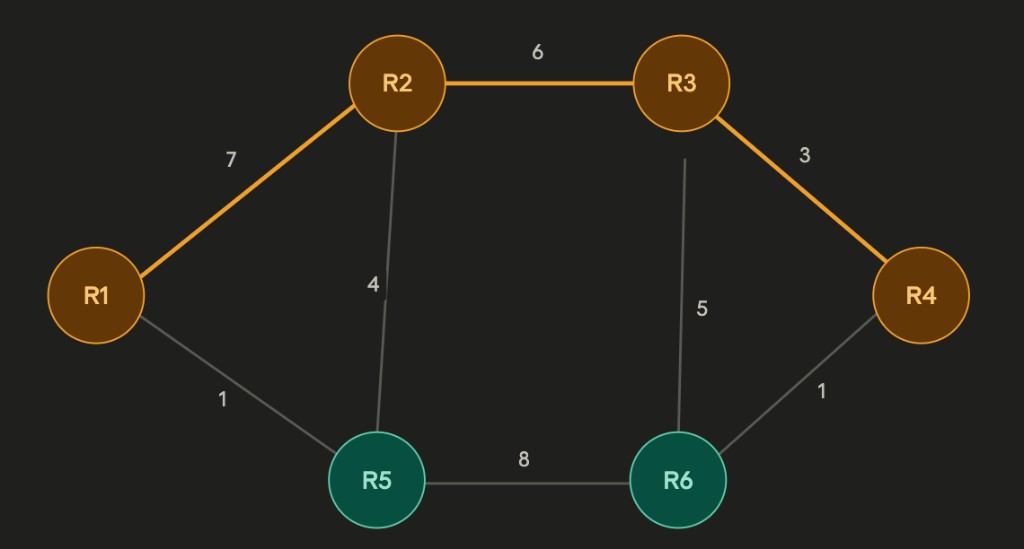
| Algorithm | Task | Data Structure |
|---|---|---|
| BFS | pathExist() — reachability within N hops | Queue + visited set |
| Prim's MST | buildMST() — min spanning tree from source | Priority queue (min-heap) |
| Dijkstra | findPath() — shortest path on MST | Priority queue + relaxation |
| Bellman-Ford | findForwardingPath() — min-cost with cost out | Distance + predecessor arrays |
| Modified Dijkstra | findPathMaxWeight() — minimise max edge weight | Max-weight tracking per vertex |
| BFS loop detect | checkLoop() — detect routing loops | Visited set per BFS root |
def findPath(self, router1, router2):
    start = self.MST.getVertex(router1)
    start.setDistance(0)
    pq.buildHeap([(v.getDistance(), v) for v in self.MST])
    while not pq.isEmpty():
        current = pq.delMin()
        if current == end: break
        for nxt in current.getConnections():
            newDist = current.getDistance() + current.getWeight(nxt)
            if newDist < nxt.getDistance():
                nxt.setDistance(newDist)
pq.decreaseKey(nxt, newDist) # O(log n)Consumption Prediction
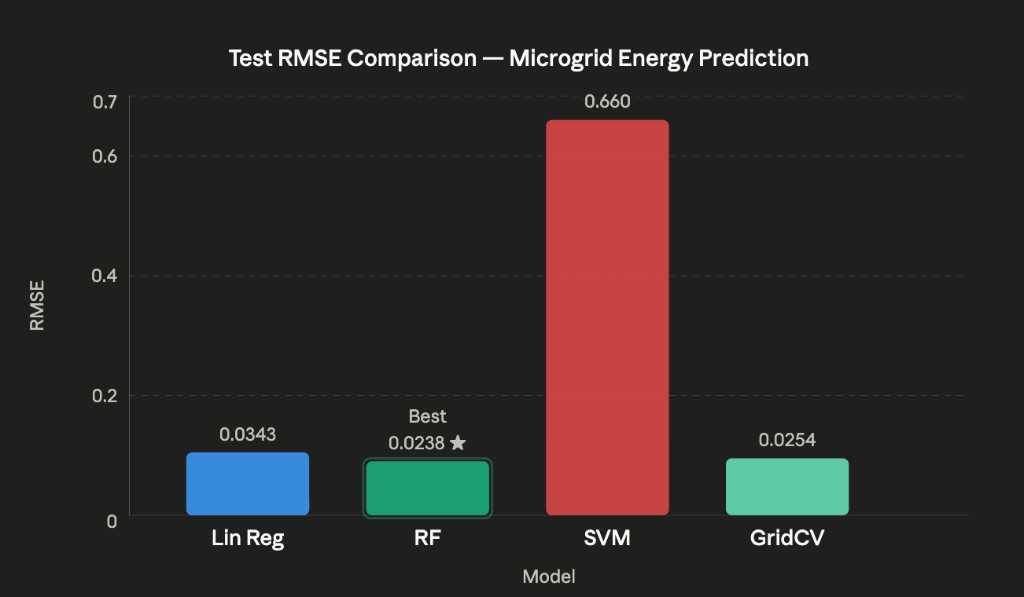
A regression-based ML pipeline predicting smart microgrid energy consumption from a 3,449-sample real-world dataset combining weather variables with power generation and consumption readings (Liège smart grid). Engineered time-of-day and cloud-coverage features, trained and compared Linear Regression, Random Forest, and SVM regressors, and applied GridSearchCV with 5-fold cross-validation for hyperparameter tuning.
Converted time column to minutes-since-midnight (continuous numeric feature)
Engineered 'clouds' = max(CD, CM, CU) across three cloud-coverage columns
Dropped correlated/redundant columns (date, time, CD, CM, CU, SNOW) post-analysis
StandardScaler normalisation applied via Scikit-Learn Pipeline before model training
| Model | Train RMSE | Test RMSE | Notes |
|---|---|---|---|
| Linear Regression | 0.0368 | 0.0343 | Consistent — no overfitting |
| Random Forest | 0.0089 | 0.0238 | Best test generalisation |
| SVM (linear) | 0.0662 | 0.0660 | Weakest overall |
| GridSearchCV (RF tuned) | ~0.0 | 0.0254 | Near-zero train — overfitting signal |
SWD (solar irradiance) and generation show near-linear correlation — strongest predictive feature
Consumption peaks at midday, validating the minutes-since-midnight engineered feature
Random Forest achieves best test RMSE (0.0238) without explicit hyperparameter tuning
GridSearchCV near-zero training RMSE (2.7e-12) confirms overfitting without bootstrap sampling
Attack & Defense
Full offensive and defensive timing side-channel study on a Raspberry Pi 5. A vulnerable password-check server leaks timing through early-exit byte comparison. A custom attacker recovers the secret password byte-by-byte using statistical timing measurements. Three mitigation strategies were designed, implemented, and evaluated in a hardened server version.
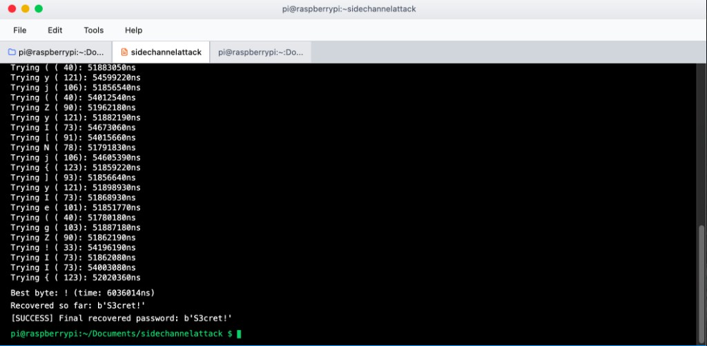
measure(candidate): opens Unix socket, sends candidate, records 120 round-trip times using time.perf_counter_ns(), applies trimmed mean (drop top/bottom 10%) to filter OS scheduling jitter
recover(): builds password byte-by-byte — character with longest average RTT indicates most correct prefix bytes matched so far
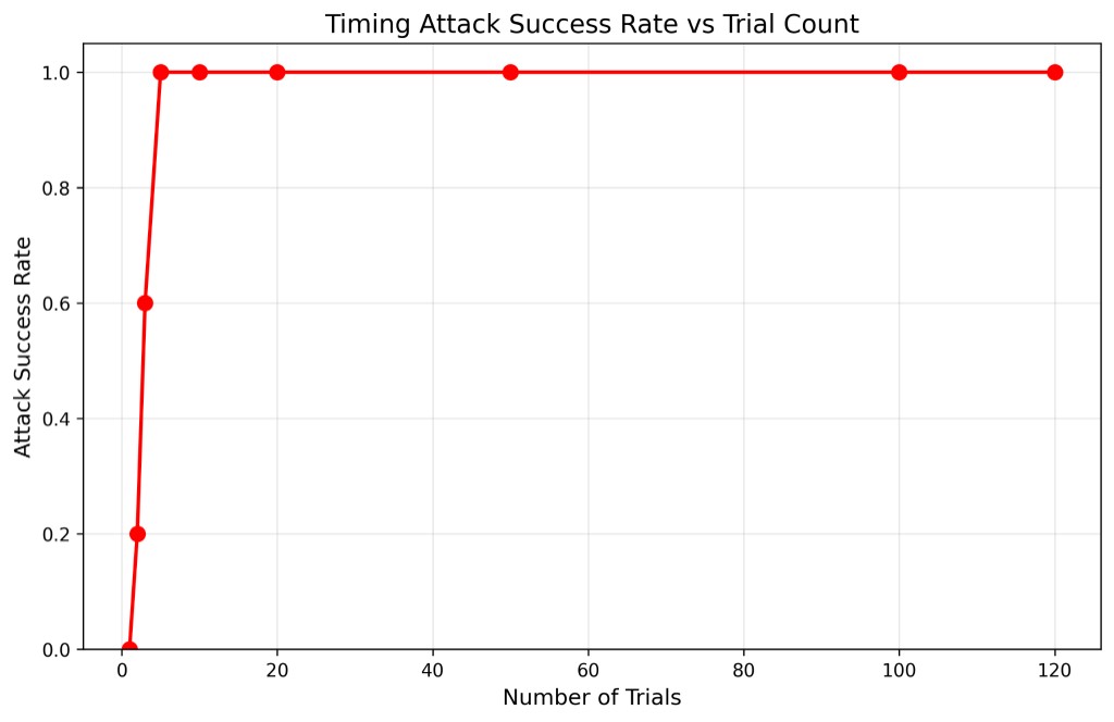
100% success at just 5 trials on Raspberry Pi 5 vs. 50+ needed on a standard laptop due to lighter background process load and more predictable scheduling
| Defense | Mechanism | Effectiveness |
|---|---|---|
| Constant-Time Comparison | XOR/OR all bytes regardless of match — no early exit | Complete |
| Fixed Timing Padding | Wait until 10ms has elapsed before responding | Complete |
| Random Delay Injection | Add random 0–5ms noise after constant-time compare | Strong |
Image Processing — DE1-SoC
A real-time software image processing system on the Altera DE1-SoC, integrating an ARM Cortex-A9 video pipeline with the FPGA video subsystem to stream, freeze, and process 320×240 RGB565 frames from a D5M camera module displayed on a VGA monitor. All image processing routines were implemented in bare-metal C using memory-mapped I/O from Linux user space.
| Stage | Component | Details |
|---|---|---|
| 1 | D5M Camera Module | Streams raw 5MP frames via TRDB-D5M interface |
| 2 | Video-In Clipper (FPGA) | Down-samples to 320×240 — QSYS IP core |
| 3 | Video-In DMA (FPGA) | Writes RGB565 frames to on-chip memory |
| 4 | ARM HPS (C code) | Reads frames via mmap() / /dev/mem from user space |
| 5 | Image Processing (C) | Applies selected filter: flip, BW threshold, invert |
| 6 | Pixel Buffer DMA (FPGA) | Sends processed frame to VGA controller |
| 7 | VGA Controller (FPGA) | Displays 320×240 output on external monitor |
Swap row i with row (H-1-i) across all columns; iterate over half the frame height.
Swap pixel (r,c) with pixel (r, W-1-c) in-place within each row.
Convert RGB565 to luminance. Set pixel white if above threshold, black otherwise.
XOR each RGB565 pixel with 0xFFFF to invert all colour channels simultaneously.
// Map FPGA pixel buffer into ARM user-space virtual memory
int fd = open("/dev/mem", O_RDWR | O_SYNC);
volatile uint16_t *pixel_buf = mmap(NULL, BUF_SIZE,
    PROT_READ | PROT_WRITE, MAP_SHARED, fd, PIXEL_BUF_BASE);

// Capture frame — 512-word hardware stride (not 320)
for (int row = 0; row < 240; row++)
    for (int col = 0; col < 320; col++)
        frame[row][col] = pixel_buf[row * 512 + col];